👉Trouble viewing the content, videos, equations or code of this email?
View it in your browser.
AIA26b: TCLab - Complementary information

Dear Student ,
I'm sending additional information for students who are using the milled version of the PCB.
Milled PCB Assembly Guide
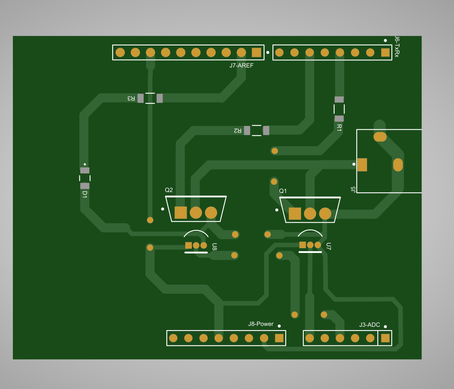
Please use the attached figures as a reference when assembling and soldering your board.
Important PCB indications:
- Red traces represent the top copper layer. These are the electrical connections that must be present on the milled PCB as copper.
- Blue traces represent required wire jumpers. Since these connections cannot be routed directly on the single-sided milled PCB, they must be added manually using short pieces of insulated wire. You can put the jumpers in the bottom layer.
- Verify all jumper locations carefully before powering the circuit.
- Use the component placement figure to identify the correct positions of the connectors, transistors, resistors, diode, and other components.
- Before connecting power, use a multimeter in continuity mode to verify the main connections and check for accidental short circuits.
Important: Blue connections are not optional. They are part of the electrical circuit and must be installed for the board to operate correctly.
Example of an assembled PCB
Please compare your assembled board with both figures before the first power-up.
Happy building! 🚀🔧
Gerardo Marx
Lecturer